QRP-Labs QMX+
This page was last updated : 20-Jul-24 10:46:52

Introduction
17 May 2024 - I own a QMX now for over a year and although I'm terrible at CW, it's a nice little rig and a great kit to build. One thing I and a few other OM's where dreaming about was a QMX in a QCX+ style case so there was more room for experiments and mods. So once in a while this was mentioned in QRP-Labs.group.io group and we kept dreaming of this great addition to the QRP-Labs product catalog.
Then out of the blue, at the FDIM in Dayton, Hans Summers releases a new product: new QMX+ multi-band multi-mode transceiver. Turns out, he has been secretly working on it for the past year. So when he added it to his webshop I didn't hesitated for a moment and ordered one.
Once again the waiting started.
When the postal services screw up aka don't handle with care
3 June 2024 - After 2 weeks, my neighbor texted me that he has accepted a package for me (for some reason the package wasn't allowed to be dropped in my parcelbox) and I was as happy as a pig in the mud.
That evening I picked it up and the joy I had first turned to fear once I opened the bag the package was put in to. It seem that my shipping from QRP-Labs got some damage to the box.


Opening the box and carefully unpacking the content which took some time (the QRP-Labs employees know how to wrap things up), it seem that there wasn't any damage.


But unfortunately after closer inspection, I found that on the mainboard C501 and L501 where damaged. Although all the parts where nicely wrapped and packed, the force placed on the package must have shifted some parts, and put force on these to parts which are the highest parts on the mainboard. :-(


C501 was torn off at the GND side taking his GND pad with him and L501 was damaged on the top top (missing 1/3 of it's top). I contacted Hans Summer through his Service Desk System and asked him if he could let me know the manufacture part number so I could order a replacement (I'm SMD capable so replacing a few SMD components is no problem). L501, seemed to be intact (resistance aprx 2 ohm), but I wasn't sure if the damaged top would negative effect the inductance. He ensured me that that damage happened to him also a few time, and it didn't have any negative effect. So that was one worry less. The C501 was a different story. He didn't have the parts in stock (his PCB's are manufactured in China and so all the parts are in the factory), but told tell me it was a standard 470uF 10V tantalum in Case D. I told him that I would hunt for the part my self at a few local suppliers, and Hans (great guy he is) offered to de-solder a cap from a stock PCB when I couldn't get any.
20 June 2024 - But luckily my local supplier could order a bunch (minim order count 5), so after a week it got a call from my supplier that he got the parts. Take a hour me- eh shack-time, I removed the damaged ground pad and make a new one by scraping of the paint of the PCB and soldering a piece of silver wire on top of it. The cap was installed and although I can't test it, I have a good feeling about it.

With that fixed I could put it aside for the next shack time opportunity.
The manual
As with every kit which Hans sells, the also was a very nice manual for the QMX multi-band multi-mode transceiver (scroll down to documentation). Chapter 1 contain a Introduction Chapter 2 contains a list building general guidelines, images of the PCB layouts (track and component placement), technical specification and the full Parts list of all components in the kit and photo's of a finished QMX+ allowing to kit builder get a idea about what to expect. And after sub chapter 2.3 Inventory parts helping the starting kit builder to identify parts, the fun starts.
Let start building
21 June 2024 - Just to be different I started with the front / control panel as mentioned in chapter 2.19 of the manual.
Control board and LCD display
I sorted all the parts, double check the PCB under my microscope and all the signal gave green,

I started with the assembly under the (not so) watch full eye of Shack cat Moppie.

Some things that came to my mind / I have done different from the manual :
- 2.20 - when soldering the female pin headers JP301, JP302 and JP304, don't try the squeeze your soldering iron between the pins. Just solder them from the side (outside / in).

- 2.21 - when installing CR2032 battery holder, I pre-tined the GND pad on the PCB a little, and pushed the CR2032 battery holder in place while heating it again, soldered the + side and after that applied a little extra tin to the GND side pad.
- 2.22 - when installing the microphone, you find out that it's hard (impossible) to place the microphone on the PCB. So I used a small piece of doublesided foam tape to fill up the space and make it easier to solder the microphone in place.

- 2.23 - when soldering the push-button switches S302 and S303, solder a non ground ping first and check the alignment of the button (it should be flat on the PCB). Soldering the non ground pin first makes it easier to adjust when needed.
- 2.24 - when installing rotary encoders S301 and S304, do what Hans write : do NOT solder the push button pins (the pair near the mounting hole) from S301 (yet, we get back to those).
- 2.25 - step 1 - I'm a rebel, I leave the protective film on the LCD ;-)
- 2.25 - step 3 - don't forget to bend the LCD tab closes to pin 1 of the LCD
- 2.25 - step 4 .. 5 - to encourage the screw through the holes of the LCD, turn them each a few turns after another, don't try to force them. (tools I used are mentioned below).
- 2.25 - step 11 - I didn't like this order. Next time I'm going to solder the header first to the LCD PCB and later to the PCB (but would stack them first using the screws and nuts to get the best alignment).
And done


Product placement ;-)
Recently I needed to replace a few (micro) screwdrivers in my shack because after more then 30 years of usage, they just worn out. I could have replaced them individually, but Amazon.nl had a good offer on the Wera 0513400001 Kraftform Micro Big Pack 1. I have used the tools before and they a great. So having some hobby budget left, I bought it for my self.
For the assembly of front panel I used:
- WERA Kraftform Micro Electronics 2069 Nutdriver for electronic applications 051181260011x 5.5 x 60 mm
- WERA Kraftform Micro Electronics 2050 PH Screwdriver for Phillips screws for electronic applications 05118023001 PH 1 x 60 mm (it's not in the set but worth having it added to it).
Hint : when you are asked if you know a (holiday, season, christmas, birthday, etc) gift, do your self a favor and ask for this set from WERA. It's a great set to have in the shack when you are into repairs.
But it's 23:00 local time, so enough for this evening.
Mainboard construction : install a bunch of true hole parts
21 June 2024 - Section 2.5 of the manual describes the 32 through-hole ceramic capacitors to be installed. I sorted all the capacitors and wrote down the value on the paper tape.
Only 2 capacitors didn't have paper tape, so I installed them first.

For the installation, I decided to work group by group. IMHO it has the following advantages :
- You work in small iterations keeping a overview what you are doing.
- You keep track of the parts.
- You preheat the area a little making the soldering go easier (especially the GND pins).
The image above shows C522 already installed. C522 was one of the capacitors which didn't have a paper tape on the legs.
Some things that came to my mind / I have done different from the manual :
- I place the parts, bend the legs a little so they stay in place when I turn over the PCB. Then I always solder one pin of the part (or group of parts), then turn over the PCB again, check if the parts are correctly inserted (sometime they drop a little when you turn over the PCB) and adjust when needed.
- With this PCB (6 layer multi-layer PCB) it's good practice to solder the non-GND pin first, and after straiten the GND pin, trim the GND pin (not to short off course), then solder the GND leg. Remember it takes time to head everything.
- When you cut of a pin, don't let it jump away (some cutters have a small spring to prevent that). Through it away in the bin or put it in a container. This will prevent sparks flying around when you are testing on the workbench.

All C's in place.

And no parts left. So I must have done something good ;-)
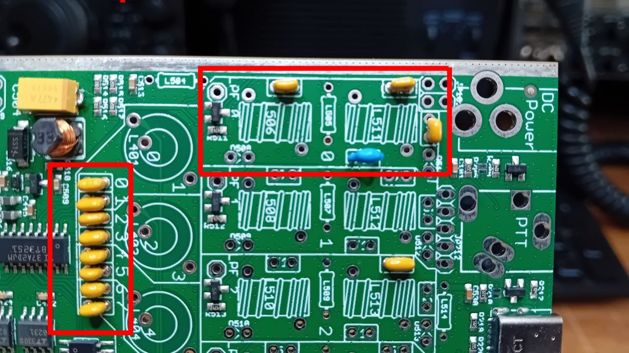
Section 2.6 describes the installation of the 12 1N4007 diodes in which Hans writes :
One lead of the diode needs to be bent over. It doesn’t matter which one, all that’s important is
that the cathode (white stripe) is correctly soldered to the pad at pointed to by the arrow. I chose to
bend the diode lead with the cathode.
I also chose to bend the diode lead with the cathode, that way, when looking at the schematic you can easily pick up the signal for and after each LPF (Don't know if the PIN diode construction is preventing this, but I will see that in the future).


All diodes are in place and allowing me to pick off the signals in the LPF section easily.
Section 2.7 describes the installation of the 8 47uH inductors. Installation is straight forward and when bend nicely no problems are to be expected.

Section 2.8 describes the installation of the BS170 PA transistors. Not difficult but it's good to read the manual.

At the bottom, the head of the M3 bolt comes quite close to IC503, so I checked it for shorts, but luckily it didn't.

2 Juli 2024 - Section 2.15 describes the installation of the rear panel connectors and a the USB-C connector touch up
Lets start with the USB-C connector touch up. Using my 1985 Olympus 10x/20x microscope I checked the USB-C connector and although it should work, it looked like it could need some additional solder. So I touched them up which took quite some ime. But IMHO it's worth doing.


Then it was time to install the AUX and PTT 3.5mm stereo pcb connectors. the BNC pcb connector and the DC pcb connector.
I soldered a pin of each of the connectors to keep them in place,

so i could use the backplane to align them.


All done.
Section 2.16 describes the Install of the right-angle front panel pin header connectors
Because I already have the front PCB assembled, I could use that to align the connectors. By soldering one of the pins on top of the main board,


After soldering the top pin, the front PCB is removed and the main board is removed from the case so the pins of the connector can be soldered.

Done
To Buck or not to Buck
2 Juli 2024 - And Buck it is....
Section 2.17 describes the installation of the power supply boards
First you need cut of a part of the female connectors. And after that the pins needs to be squeezed a bit together so it can be soldered to the power supply boards.


Next the 2 nylon bold and nuts are installed.

Next the power supply boards with the (still not soldered) female connector placed over the angle male connector.


With the top nuts installed the power supply stay in place and the main board can be flipped over. Allowing soldering the angle male connectors.

With the male connectors soldered, we flip back the main board to solder the female connectors to the power supply boards.

With the top pins of the female connector soldered, I removed the power supply boards so I could solder the bottom pins.

And done.
Section 2.18 describes the Installation of the Audio and Paddle connectors
Placing 3.5 mm stereo PCB connectors on the PCB and using the assembled front panel, I aligned them.


Using silver plated copper wire, i made 2 bows to align the audio board to the main board. First solder the bottom part of the bows and after that bending the bow pins a little, the boards are held together. Then the top pins are solder and trimmed.


Then all the other pins are soldered in using silver plated copper wire.


Next step, lots of transformer and toroid winding.
Mindfull toroid winding
3 Juli 2024 - Section 2.13 describes the winding and the installation of trifilar toroid T401
Hans writes a good technic on how to twist the 3 wires. But I used my "simple wire twist tool" to give the twist a nice and even spread.

Although Hans writes that you can easily burn of the enamel from a enamal wire a blob of tin on your soldering iron tip, I still prefer scraping it off. For that I a small stainless steel plate (other harder metals can also be used like brass or normal sheet metal), a small C clamp and a small hobby knife.

More info about this Technic can be found on this page.
After identifying the wires I cut them in 3 different lengths, that way I can identify the wires and also it makes installing the toroid easier.

pulling the wires through the holes, some solder . . .


and we are done for T401.

Section 2.11 describes the winding and the installation of the Band Pass Filter toroids L401, L403-L405.
Not difficult but it's good to read the manual.


Installation is quite straight forward.

Then the section describes the construction of L504. It's a bit strange, but when you follow the manual its no problem.
Only thing you have to take care of is that you don't have to much exposed make a short between the blue toroid wire on hole 6 and the pink toroid wire on the hole 0

So don't do as I done below, I had to do some re-winding on the pink toroid.

But after that it was all good.

Section 2.10 describes the winding and the installation of L502
Not difficult but it's good to read the manual. Only thing i did do is pre-tin the wires. The holes where big enough to accept the (slightly) pre-tinned wire (I used a piece of spare wire to test it).


Next step, winding the two transformer and the LPF toroids.
Again mindfull toroid winding
7 Juli 2024 - Section 2.12 describes the construction and installation of the Low Pass Filter toroids
On a Sunday morning, while the rest of the house was still sleeping, I fired up the oven for the kaiser rolls and croissants, made coffee and tea, and set the table for breakfast.
And when that was done, there was some time for mindful toroid winding.


All LPF toroids, ready to be installed. The installation is straight forward and only aprx 3/4 of a hour.


The result
8 Juli 2024 - Section 2.14 describes the construction and installation of transformer T507
TODO ADD TEXT


TODO ADD TEXT
Don't forget to install the jumper wire on JP501.

Section 2.9 describes the construction and installation of transformer T501
Important note: Hans made a separate manual for constructing the Output tranformer for QRP Labs transceivers: QDX, QDX-M and QMX.
TODO ADD TEXT


Smoke test and loading firmware
9 Juli 2024 - And then it was time to setup the powersupply and hook up everything. Switching on the power and . . . nothing happens.
Oh wait, you have to press the upper rotary encoder to power up the QMX+.


My Linux computer finds the QMX as removable drive and after copying the QMX firmware file to that drive, the drive disappear and the QMX+ is booting. VICTORY!!!!!


It starts with the QMX 80-20m band version and after rotating the tune knob we have the QMX+ 160-6m band version. A short press on the Tune knob and it's showing the 160m band.
Are we finished? No not yet, there is still a piece of hardware to install. The QLG3 GPS option.
QLG3 GPS option
Section 4 describes the installation of the QLG3 GPS option.


TODO ADD TEXT


TODO ADD TEXT

Yes we are good to go. Logging into the QMX+ with Putty, configuring the GPS as being internal, going to diagnostics only to see . . . . nothing :-(
Is there a short? Did I forget something? Oh I did, what is missing in the above pictures? Indeed a picture of soldering the female header to the mainboard.

Ok, that can be fixed quickly and after that diagnostics is showing GPS sats all over the place :-)
So now we are ready to do some real testing.
How much does it throw?
Using my OZ2CPU digitale RF mW-dBm-mV meter in combination with the -40dB RF Sampler I will measure the power output for the various bands.

40m output power.

The power outputs where (for 9V):
- 160m - 5.75 W
- 80m - 5.00 W
- 60m - 4.47 W
- 40m - 4.47 W
- 30m - 4.57 W
- 20m - 3.09 W
- 17m - 2.57 W
- 15m - 2.88 W
- 12m - 2.14 W
- 11m - 3.24 W
- 10m - 2.95 W
- 6m - 2.09 W
Boxing it up
The last step for this build was boxing it all up. And for that I followed Hans his manual section 2.27.
Well I cheated on that one, I used the case as a assembly holder and to align the connectors when installing them. ;-)

First time FT8
A good way to check your rig is to run a few FT8 session with it. First RX and after that TX.
I started on 40m which was kind of busy. RX went good, and after a few minutes I called YL3CW. And first call he responded.

RX map on PSKReporter.

TX map on PSKReporter.

Then it was time to try 20m. There wasn't much activity, but busy. RX went good, and after a few minutes I called Y04NF. And first call he responded.

RX map on PSKReporter.

TX map on PSKReporter.

Enough for today. A large storm is coming in, so it's time to disconnect the antenna's and have a cold drink.

Tilting feet
13 Juli 2024 - Like all the cases from QRP-Labs, I really love the QCX+ / QMX+ case. But when you the have QCX+ or QMX+ case it on a desk, the ergonomics aren't that good. Just try to turn the tuning dial and you feel what I mean.
But luckily I already solved this problem with my QCX+ and with my experience on the QCX-Mini I desiged to re-design the original QCX+ tilling feet so, the they could be used with strong doublesided tape.
And after aprx 2 hour of 3D printing (0.12 mm layer height and 60% infill) they where ready.

For the double sided tape I going to use this tape from Aliexpress or if the link is broken, google for "hxres tape".


I have very good experience with this tape, it's strong like hell, but this is the first time I tried it for the tilt feed. So success is defiantly not guaranteed.

The height of the 3D printed tilt-feed is the same as the rubber feet supplied with the QMX+ case. So no wobbling whats so ever.


Now the ergonomics is much better when using the QMX+ on the desk. For now I leave it stand on the work bench for a day and if tomorrow morning the case is still in this position, the tape as approved for this job :-)
14 Juli 2024 - And 24 hours later, it's still standing so this tape can handle it and is approved for this usage :-) 
Enough building, modifying for now, lets make some QSO's.
To be continued . . . . .
My tips
Some tips I would like to share:
- Don't work on the QMX+ late at night.
- Read the manual (twice) before soldering.
- Take regular breaks with a beverage of your choice (alcohol based beverage, may seem to relax, but also might cloud your skills).
- Become a member and read the posts on the QRP-Labs groups.io group.
- And above all, take your time when building kits. Remember, it's not a race who finished it first, it's a hobby to enjoy.
But these tips are just the tip of the ice berg.
Previous page: QRP-Labs QMX
Next page: OZ2CPU digitale RF mW-dBm-mV meter