WB2CBA LPF Adapter for NanoVNA
This page was last updated : 14-Sep-23 18:06:44
Introduction
Fellow ham and hamradio homebrewer Gilles F1BFU bought 2 adapter kits of my for his experiments. After a few months he ordered 2 additional kits for a friend and told me that he was working on a uSDX version designed by Barb WB2CBA design. He asked me if I could design a adapter that could fit the WB2CBA LPF for measurements and when I told hem I could take a look at it if I had a LPF PCB he send me a bare PCB.
A new adapter
And so anther adapter got designed.
NOTE : Although the schematic is ok, in the PCB design there is big failure (try not to laugh we get to it)

When the design was ready I ordered a batch prototype PCB's and when they arrived I assembled one.

Build a 20M LPF

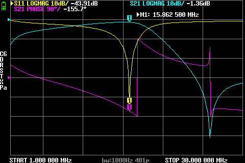
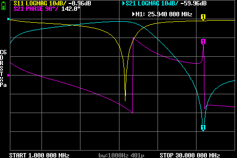
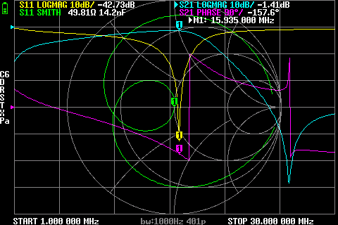
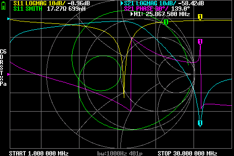
Hooked it up to my NanoVNA and toke a look at the LPF response.


Because this type of filter was unkown to me I simulated it in the online circuit simulator CircuitLab.

(click on the graphs for more details)
It seems that the LPF response was as designed.
So what was the big design failure ?
The big design failure and a new design.
And the big design failure was : the WB2CBA LPF filter is installed up-side down (why didn't I read the uSDX construction manual?)
So I needed to modify the design to correct this error and had to ordered another prototype batch of PCB's.

So when the new PCB's arrived I assembled one

Removed the headers from the LPF and installed them on the component side as Barb WB2CBA intended.


The response is as expected.


3D printed base plate.
The PCB has the same size as the QRP-LABS H4 adapter so that plate can be used.

The 3D base plate design is publicly available so you can print your own but licensed it Attribution-NonCommercial-NoDerivs 3.0 Unported (CC BY-NC-ND 3.0).
Meaning :
- Attribution — You must give appropriate credit, provide a link to the license, and indicate if changes were made. You may do so in any reasonable manner, but not in any way that suggests the licensor endorses you or your use.
- NonCommercial — You may not use the material for commercial purposes.
- NoDerivatives — If you remix, transform, or build upon the material, you may not distribute the modified material.
It's not to be childish but it now happened a few times that a 3D design I made was sold by other people just because is was "Open source, so I can do anything I want with it" without any credits or even a token of appreciation.
When you want it to be used Commercial, please contact me.
And again it looks new and shiny.
Update 28 may 2022
In this uSDX groups.io post OM Kevin K3TL wrote :
When sweeping the mOnO filter boards out of the unit, the capacitance of the 3 FETs will not be present and i believe should be added back by affixing a 150 to 180 pF cap across TD and GND on the test fixture 73, Kevin K3TL
This can be easily done by soldering the needed capacitor in a 2 pin header connector. And after calibration place it on the SHORT jumper place.
Parts needed : capacitor of choice (for this construction I used the 150 pF), 2 pin female header connector

I use a crimping tool to pre-crimp the connectors (but not complete crimp them). Solder them with just a tiny bit of solder (you don't want solder flowing into the connector part).

Check if it still fits (it did)

And it's ready to use. But don't forget, calibrate your adapters without this capacitor inserted.

Where to buy
I have ordered a larger batch of PCB's and sell these bare PCBs (physical and gerber files) and also kit or ready build and tested versions. When you interested use the form on the For-Sale page.
When they are sold out and there is a demand, I might be ordering a new batch of PCB's to sell them, make new kits or even sell full assembled adapters. So when they are sold out and your interested, let me know through the Contact form.
User Gallery
When people buy one of my PCB's, kits etc. I ask then if they send me a picture when they build it or using it. Below you find images some OM's send me.
OM's thanks for the pictures. All pictures (c) to the OM.
Patrick ON7ET
When Patrick ON7ET received his package he send me e-mail.
Dear OM Lex,
I received the package today.
I tried the adapter for NanoVNA with two serial resonance LPF modules already built for my uSDX.
One word to say: perfect!
For the 80m module, I was able to adjust the attenuation of the second harmonic down to -64.14 dB.
For the 40m module, I was able to adjust the attenuation of the second harmonic down to -61,88 dB.
I still have several modules to build and adjust then, I will keep you informed of the results.
See attached photos, they speak for themselves.
For the crystal tester, you will have to be patient to receive my feedback, because my priority is to finalize the LPF modules for my uSDX.
Thank you for the excellent quality of realization of your adapters.
Continue on the same path, keeping the work at a high level.
Good evening.
73 de Patrick - ON7ET
10m second harmonic 76dB down
15m second harmonic 73dB down
20m second harmonic 77dB down
40m second harmonic 64dB down
80m second harmonic 62dB down
Thanks for sharing the pictures and the compliment Dr OM Patrick. You got great results out of your LPF's.
Previous page: Component Measuring Adapter for NanoVNA
Next page: Nifty 3.5mm jack socket tool


