K2 BPF aligment with a NanoVNA
This page was last updated : 31-Jul-22 22:35:18
This page is work in progress

The used Elecraft K2 I got my hands on needed some work on the 20m band and for the alignment of the 20m BPF I could follow the Elecraft manual. But owning a NanoVNA . . . . . well you know where this is going ;-)
A simple idea.
The idea is simple : inject signal into the BPF and measure what is coming out. You have to find the correct spots to inject and pick it up and looking at schematic and knowing that the BPF's in the K2 are symmetrical, it doesn't matter from which side we are injecting the signal so we can inject the signal at J13 pin 5 (or at pin 3 when jumper W6 is installed).
In this image the J13 header pins are counting down (so left starts at 8 and counts down to 1 on the right). The pin on the right, closest to the cabinet, is the GND.

When we follow the path through the BPF's, we get to the sheet terminal BPF which points RF schematic sheet nr 2.
That sheet terminal is connected to the junction of D6, D7 and R5.

So the pickup point of the signal is the junction D6, D7, R5. I soldered a left over pin from the header used above to this junction (in my case to the cathode of D7).

To prevent overload of the system, I used inline 2 attenuates (10dB and 20dB) to get the +6dBm output signal of my NanoVNA to a more safe -24dBm (aprx 3.9uW / 40mVpp / 14mVrms).
Also I setup my K2 with ATT on and PRE off, which are just safety precautions. According to the datasheet, the TUF-1 mixer could handle it, but better safe then sorry.
My K2 was equipped with a header for the XVerter Interface in which the previous owner inserted a relay based PTT circuit. Because of the iritating switch noise when doing CW I removed the circuit and inserted a bypass header. So I only had to make a header to which I could connect the header connector of my test cable (a short piece of RG-174 with a SMA and a 2 pole header connector).
My NanoVNA H4 with the 2 attenuates on the S1 port and with my test cables connected.

My highly professional calibration tool for these test cables (LOAD, THRU, SHORT).

Let's start measuring
When you want to align the BPF's in your rig, please follow the warning below :
WARNING : DON'T MEASURE WITH YOUR NANOVNA IN A POWERED UP DEVICE.
Because the K2 is using latch relays, it is easy to select a BPF and keep it in line without keeping the rig powered up. So without the NanoVNA connected I powered up the rig, select the desired band, and switch the rig off.
For every band I re-calibrate the NanoVNA with a center frequency of the mid of the selected band and with a 1MHz span and store it. The 1MHz span is big enough to see the change in the BPF response and because the calibration is stored, I could switch to a wider span to get a wider view and switch back to the calibrated span after that.

Not only did I adjusted the 20m BPF, I also adjusted the other BPF's in the little rig.
The results
With the latest Dislord firmware on my NanoVNA-H4 I can save calibration sets and screenshots by name. So in the future, when I use the same cables, I can re-call the calibration sets to re-do the measurements.
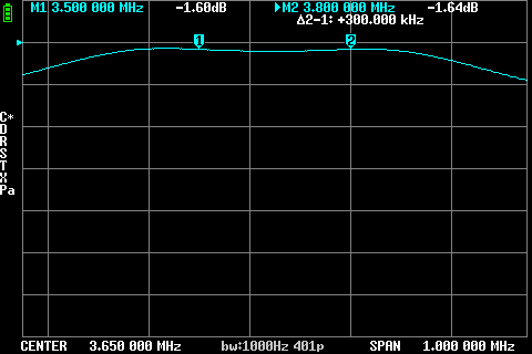
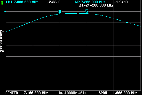
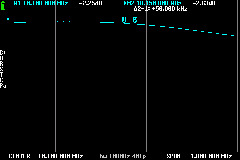
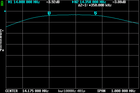
Below you find screenshot of the BPF's after alignment. What I noticed is that the BPF's have a higher loss the higher the selected band. That's maybe something to dive deeper in to,.
80M BPF
In the near future, I'm going to try to get it more flat.
40M BPF
In the near future, I'm going to try to get it more even.
30M BPF
Because of the dependency of the 20m and 30m BPF's, I want to take another look at it to see If I can get a better response out of both.
20M BPF
Because of the dependency of the 20m and 30m BPF's, I want to take another look at it to see If I can get a better response out of both.
17M BPF
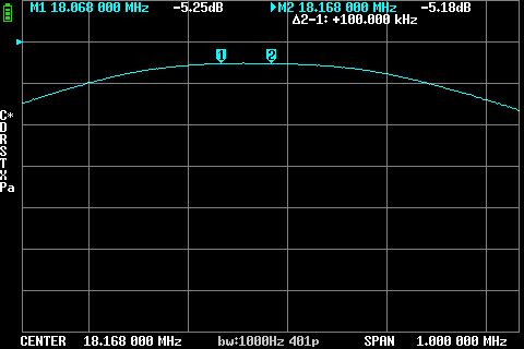
15M BPF
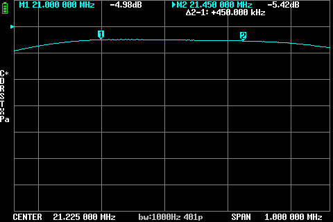
12M BPF
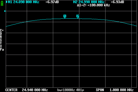
10M BPF
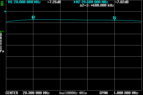
Power output
I set my K2 to a power output of 2W with the Power dial giving me the results below :
- 80M - 2.8W
- 40M - 2.6W
- 30M - 2.5W
- 20M - 2.3W
- 17M - 2.2W
- 15M - 2.2W
- 12M - 2.2W
- 10M - 2 W
This looks very good and could be inline with the BPF results as shown above.
Overall conclusion
Aligning / adjusting the BPF's with a NanoVNA is quite easy.
Pro
- You are seeing what you are doing.
- You can get the max out of the BPF's
- K2 has latch relays, so when powered down the selected BPF stays inline.
Con
- You have to do solder in your K2 (but hey you got a K2, a soldering iron is mandatory).
- You have to remove the NanoVNA connections between switching bands.
- You have to power up and power down when you want to switch bands.
- You have to calibrate your NanoVNA for every band *1
*1 : If your NanoVNA supports a SD card with the latest Dislord firmware, you can pre-calibrate and safe the calibration data to names sets on you SD-card.
If your NanoVNA doesn't support a SD card, pre-calibrate the set and store them into you NanoVNA in slots 1 .. 6. This will safe a lot of time.
Update 2022-07-31 :
In the Elecraft Groups.io group, Lou W7HV wrote :
Very nice! One thing as a matter of convenience. I do one 401 point calibration on my V2Plus4 for the entire HF range and save it on the nanoVNA. I then use that for all subsequent HF work, even much higher resolution scans. The response of the nanoVNA is smooth over that range and it interpolates calibration points between the original 401 points as needed. I've check it periodically, and it has remained stable over the past year. Unlike UHF, in HF benchwork, the changes in the calibration plane rarely changes enough to make a difference.
If this works out, you could stick a big number of calibrations steps once you have calibrated the NanoVNA for 1 to 30MHz. So I'm going to test this.
To be continued. . . . . . .
Previous page: K2 USB interface
Next page: K2 won't shut up.
